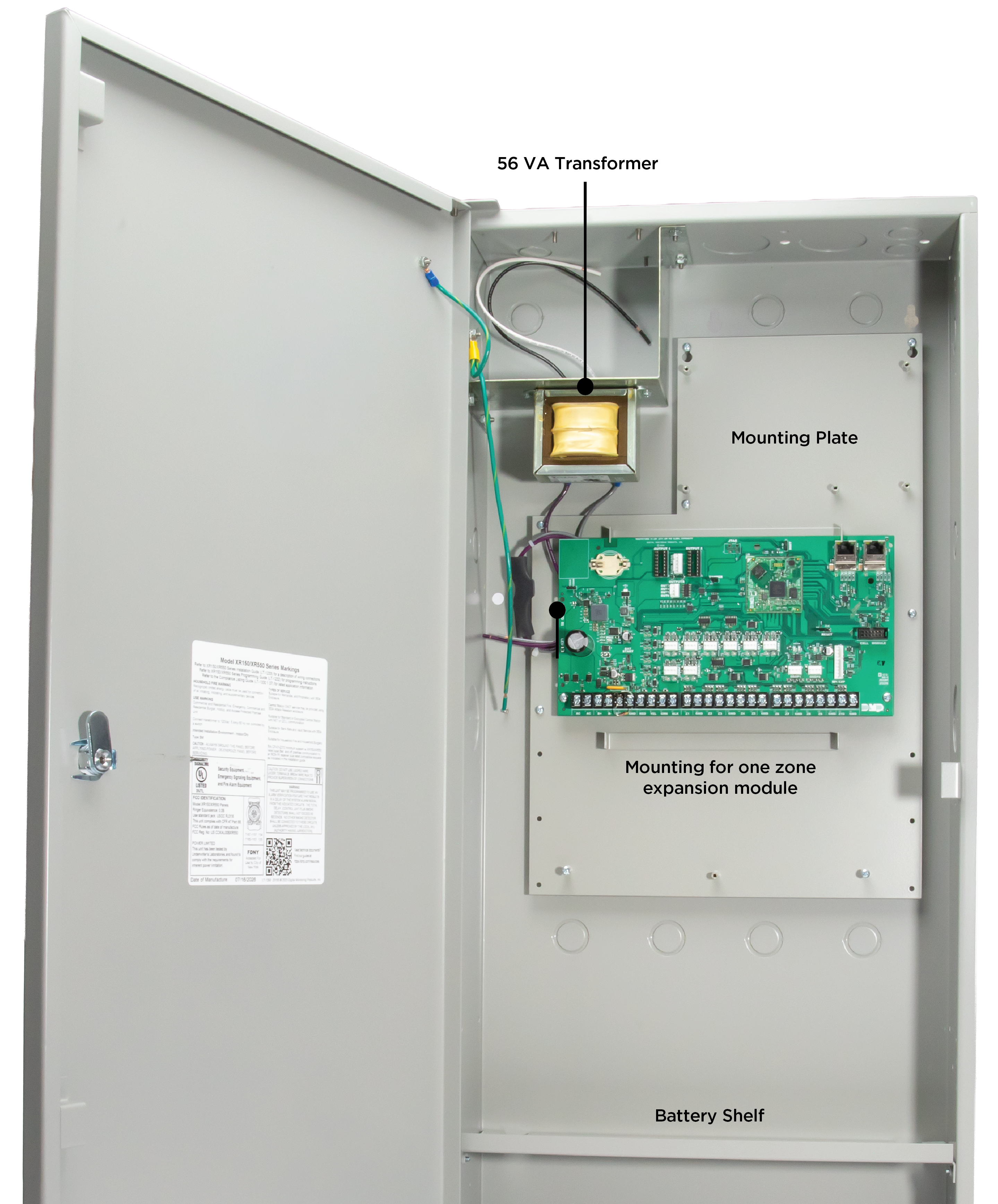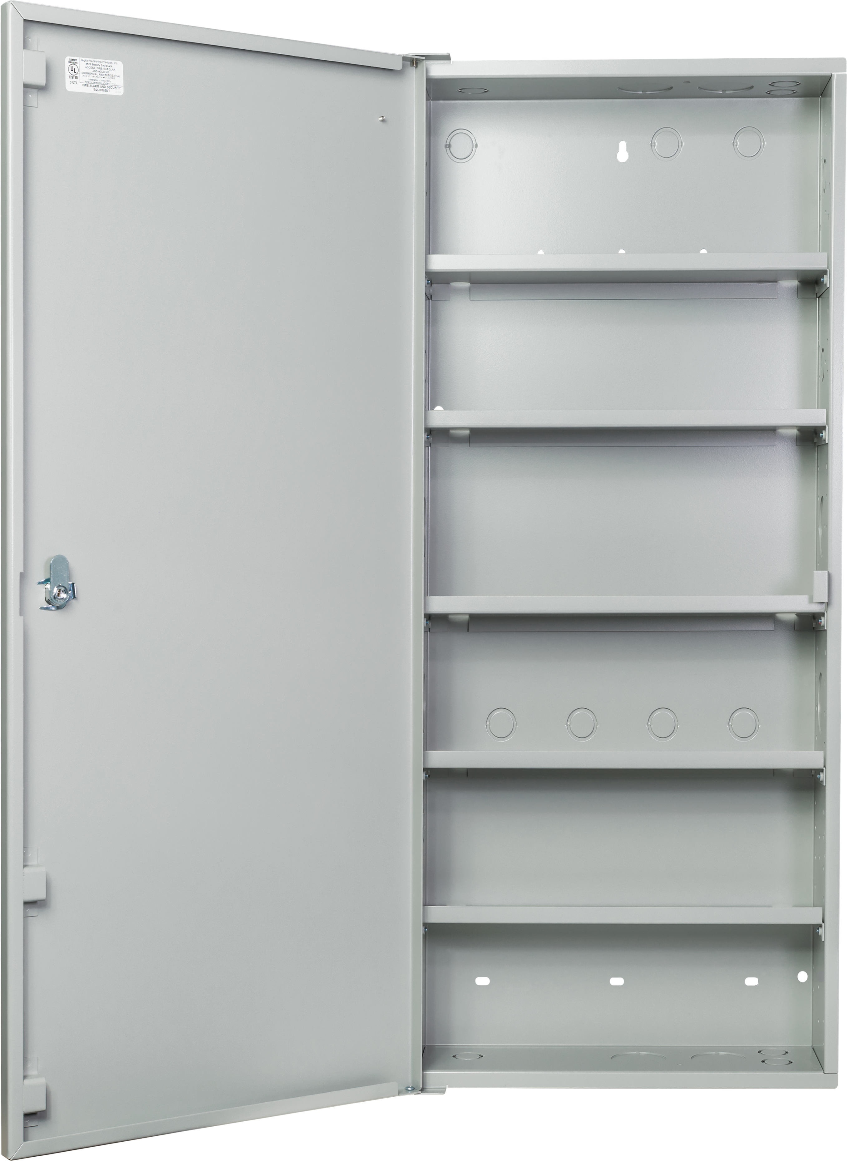

XR650 Installation and Programming Guide
Breadcrumbs

Install the Panel

Step 1: Mount the Enclosure

Note: It is not necessary to remove the panel PCB when installing the enclosure.

Mount the XR650 metal enclosure in a secure, dry place to protect the panel from damage due to tampering or the elements.

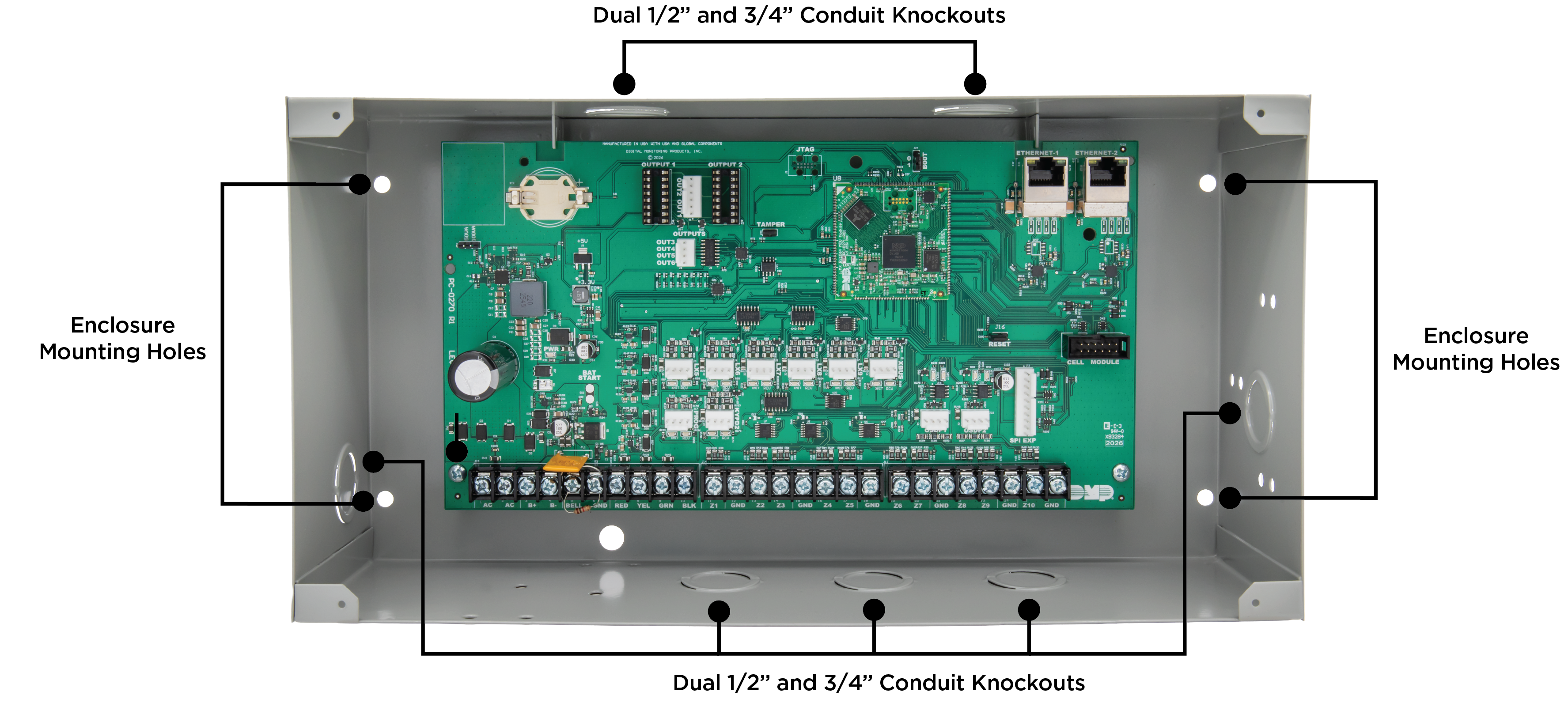
See the diagrams below for the positions on the enclosure that can be added. Fill each additional knockout with conduit.

Model 350 or 350A Enclosure

The 350A Attack Resistant enclosure is factory shipped with one knockout on the top-left of the enclosure. As needed, additional knockouts or antenna exits may be added at the time of installation.
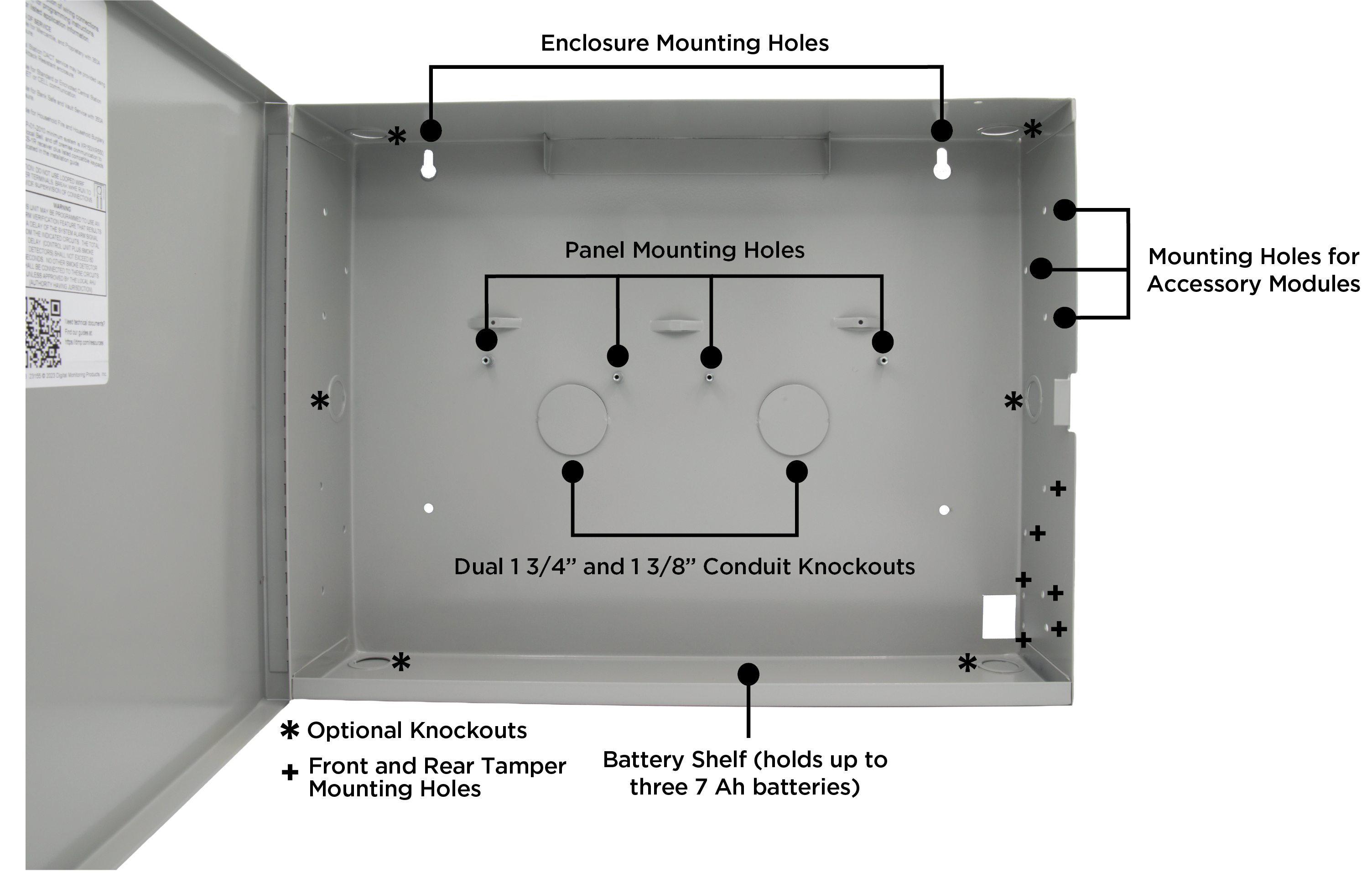
350A enclosure.png
Model 341 Enclosure

The 341 also includes a lid with PEMS for an optional battery bracket. Refer to the 341 Enclosure Installation Sheet for more information.
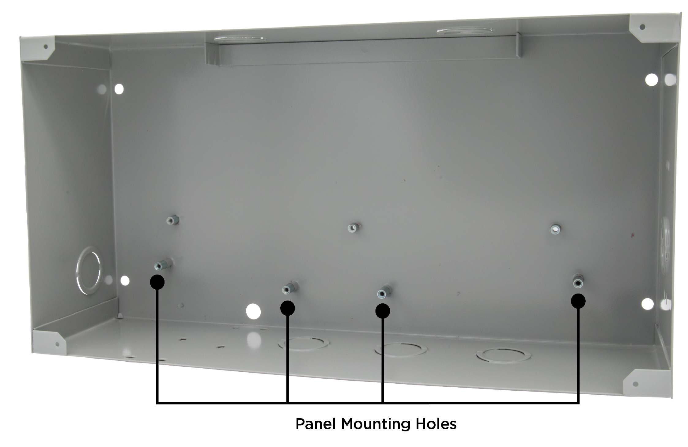
341 standalone.png
XR650 in 341.png
Model 352X Enclosure
XR650 in 352X.png
352S Enclosure with Shelves
352S_04.png

Step 2: Mount the Keypads

DMP keypads have removable covers that allow the base to be mounted on a wall or other flat surface using the screw holes provided on each corner. For solid-wall installations or applications requiring conduit, use a DMP 695 or 696 Keypad Backbox.

Refer to the 695-7800 In-Wall Backbox Installation Guide for more information.

Keypad Specifications

Several factors determine the performance characteristics of the keypad bus, including wire length, the number of connected devices, and the voltage at each device. When planning a keypad bus installation, consider the following information:

  • Wire type — DMP recommends using 18- or 22-gauge unshielded wire for all LX-Bus, AX-Bus, and keypad bus circuits. Do not use twisted-pair or shielded wire for LX-Bus, AX-Bus and keypad bus data circuits.

  • Auxiliary power — To maintain auxiliary power integrity on keypad bus circuits, do not exceed 500 ft when using 22-gauge wire or 1,000 ft with 18-gauge wire. To increase the wire length or add devices, install an additional power supply listed for power limited and regulated
    (12 VDC nominal) with battery backup.

  • Keypad capacity — Each panel supports a specific number of supervised keypads. Add additional keypads in the unsupervised mode. The XR650 supports up to 16 supervised keypads.

  • Maximum bus length — The maximum distance for any one bus circuit is 2,500 ft, regardless of wire gauge. This can be one continuous run or multiple branches, as long as the total wire length does not exceed 2,500 ft. As wire distance from the panel increases, the DC voltage on the wire decreases. The first 2,500-foot circuit supports a maximum of 40 LX-Bus and AX-Bus devices.

  • Maximum voltage drop — The maximum voltage drop between the panel (or auxiliary power supply) and any device is 2.0 VDC. If the voltage at any device is below the required level, add an auxiliary power supply at the end of the circuit. Devices may not operate properly when the voltage is too low.

Refer to the 710 Bus Splitter/Repeater Module Installation Sheet or the Trouble-Free LX-Bus and Keypad Bus Wiring Application Note.

Step 3: Wire the Power Supply

Wire Primary Power Supply

AC Terminals 1 and 2

Connect the transformer wires to terminals 1 and 2 on the panel. Use no more than 70 ft of
16-gauge wire or 40 ft of 18-gauge wire between the transformer and the panel.

CAUTION: Ensure the panel is properly grounded before connecting any devices or applying power to the panel. Proper grounding helps protect system components against electrostatic discharge.

See Earth Ground (GND) for more information.

Transformer Types

Use one of the following transformers:

  • Model 327 — 16.5 VAC, 50 VA plug-in transformer

  • Model 322/323 — 16 VAC, 56 VA wire-in transformer

  • Model 324/324P — 16 VAC, 100 VA wire-in transformer.

Use Model 322/323 or 324/324P wire-in transformers when required by the Authority Having Jurisdiction (AHJ).

CAUTION: Connect the transformer to an unswitched 120 VAC, 60 Hz electrical outlet with at least 0.87 A of available current. Never share the transformer output with any other equipment.

50 VA–100 VA Transformer Selection

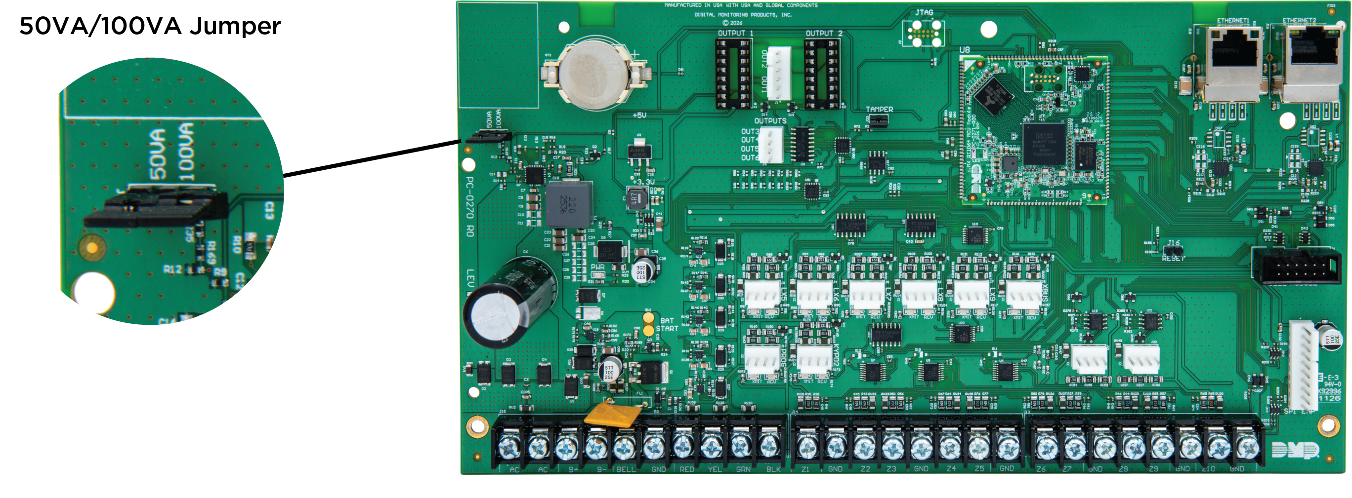
A 3-pin header allows you to select the transformer type and corresponding maximum current.

  • 50 VA — Place the jumper on the left two pins labeled 50 VA. This setting supports a maximum of 2.5 A for bell, battery charger, and all other external interfaces when using Model 322/323 (56 VA) or Model 327 (50 VA) plug-in transformer.

  • 100 VA — Place the jumper on the right two pins labeled 100 VA. This setting supports a maximum of 5 A bell, battery charger, and all other external interfaces when using Model 324/324P (100 VA) wire-in transformer.
transformer setting jumper.png
Wire Secondary Power Supply

Battery Terminals 3 and 4

  1. Connect the black battery lead to the negative (-) battery terminal. The negative terminal connects to the enclosure ground internally through the XR650 circuit board.

  2. Connect the red battery lead to the battery positive (+) terminal.

  3. To add a second battery in parallel, use the DMP Model 318 Dual Battery Harness. DMP requires each battery to be separated by a Positive Temperature Coefficient (PTC) switch in the battery harness wiring. This protects each battery from a battery reversal or short circuit.

CAUTION: Do not use gel cell batteries with the XR650 panel. Use sealed lead-acid batteries only.

Use any of the following DMP sealed lead-acid rechargeable batteries:

  • Model 364 — 12 VDC, 1.3 Ah

  • Model 365 — 12 VDC, 9 Ah

  • Model 366 — 12 VDC, 18 Ah

  • Model 368 — 12 VDC, 5 Ah

  • Model 369 — 12 VDC, 7 Ah

DMP batteries have been tested to ensure proper charging with DMP products.

Earth Ground (GND)

The XR650 panel terminal 4 can be connected to earth ground (if available) using 14-gauge wire or larger. You can also connect terminal 4 to a cold water pipe or ground rod.

An earth ground connection is not required for normal system operation.

CAUTION: Do not use gas pipes, sprinkler pipes, electrical ground connections, or server racks for grounding.

To provide ground fault detection, use the DMP Model 271 Ground Fault Detection Module. The module detects ground faults without damaging the panel. Connect the module to a zone and to the earth ground (if available) using 14-gauge wire or larger to detect a ground fault.

Refer to the 271 Ground Fault Detection Module Installation Guide for more information.

Battery Only Start

When powering up the XR650 using battery power only, briefly short the battery start pads to activate the battery cutoff circuit. The lead requires a momentary short only. Once the battery cutoff circuit activates, the battery voltage keeps the circuit engaged.

When powering up the XR650 with an AC transformer connected, the battery cutoff circuit activates automatically.

Battery and Power Requirements

Battery Replacement

DMP recommends replacing the battery every 3 to 5 years under normal operating conditions.

Battery Charging and Supervision

Discharge/Recharge

The XR650 battery charging circuit provides a float charge of 13.8 VDC at a maximum charging current of 1.0 A when using a 50 VA or 56 VA transformer.

The following table shows the battery voltage levels associated with each condition:

Condition

Voltage Level

Battery Trouble

Below 11.9 VDC

Battery Cutoff

Below 10.2 VDC

Battery Restored

Above 12.6 VDC

Battery Supervision

The XR650 monitors the battery when AC power is present. The panel performs a battery test every 3 minutes, with each test lasting 5 seconds. During the test, the panel places a load on the battery to measure its voltage.

  • If a battery voltage falls below 11.9 VDC, the panel detects a low-battery condition.

  • If AC power is not present, the panel detects a low-battery condition when the battery voltage drops below 11.9 VDC.

  • If a low-battery condition is detected while AC power is present, the panel repeats the battery test every 2 minutes until the battery voltage rises above 12.6 VDC. At this level, the battery is considered restored.

  • If a weak battery is replaced with a fully charged battery, the panel does not recognize the restored battery voltage until the next 2-minute battery test is complete.

Battery Cutoff

The XR650 disconnects the battery when the battery voltage drops below 10.2 VDC. This protects the battery from damage caused by deep discharge.

Power Requirements

During an AC power failure, the XR650 and all connected auxiliary devices draw power from the battery.

Refer to the Standby Battery Tables below for XR650’s power requirements. To calculate the total system current, add the current draw of the XR650 and all connected devices, including keypads, zone expansion modules, and other auxiliary devices. Multiply the total system current by the required standby time in hours to calculate the required battery capacity in ampere-hours (Ah).

Note: Include the power requirements of all devices connected to the system when calculating battery standby capacity.

See the Battery Calculator for complete battery capacity calculations.

Standby Battery Selection

Use the Battery Amp Hours Required value calculated in the Battery Calculator to determine the battery size and number of batteries required for 24, 60, or 72 hours of standby power.

  1. Select the required standby time: 24, 60, or 72 hours.

  2. Select a battery size from the available options:

    • Model 364 — 12 VDC, 1.3 Ah (when installed in the Model 341 enclosure)

    • Model 365 — 12 VDC, 9 Ah

    • Model 366 — 12 VDC, 18 Ah

    • Model 368 — 12 VDC, 5 Ah

    • Model 369 — 12 VDC, 7 Ah

  3. In the standby battery table below, find the Max. Ah Available value that is equal to or greater than the calculated Battery Amp Hours Required value in the Battery Calculator.

Note: If the Amp Hours Required exceeds any Max. Ah Available value in the table, add one or more power supplies to reduce the required amp hours.

See the 710 Bus Splitter/Repeater Installation Guide for more information.

Transformer and Enclosure Requirements

The following transformer configurations are supported:

  • The Model 327 Plug-in 50 VA or Model 322/323 Wire-in 56 VA transformer can be used with up to 36 Ah of batteries.

  • The Model 324/324P Wire-in 100 VA transformer can be used with any of the battery configurations listed in the standby battery table.

For listed installations, install the batteries in a DMP Model 349, 350 or 352S enclosure. All wiring shall run through conduit. The enclosure shall be installed to the left of the XR650 enclosure to ensure battery and AC wire separation.

Standby Battery Tables

24 Hours of Standby Power*

5.0 Ah Batteries

7 Ah Batteries

9 Ah Batteries

18 Ah Batteries

Max. Ah Available

No. of Batteries

Max. Ah Available

No. of Batteries

Max. Ah Available

No. of Batteries

Max. Ah Available

No. of Batteries

8

2

6

1

8

1

16

1

12

3

12

2

16

2

32

2

16

4

18

3

24

3

48

3

20

5

24

4

32

4

64

4

24

6

30

5

40

5

80

5

28

7

36

6

48

6

88†

6

32

8

42

7

56

7


36

9

48

8

64

8

40

10

54

9

72

9

44

11

60

10

80

10

48

12

66

11

88

11

52

13

72

12


56

14

78

13

60

15

84

14

64

16


68

17

72

18

76

19

80

20

84

21

88

22

*48 hours is the typical battery recharge time for any of the Number of Batteries shown in this section.

†88 Ah is 5x 18 Ah and 1x 9 Ah.

72 Hours of Standby Power*

9 Ah Batteries

18 Ah Batteries

Max. Ah Available

No. of Batteries

Max. Ah Available

No. of Batteries

8

1

16

1

16

2

32

2

24

3

48

3

32

4

64

4

40

5

80

5

48

6

96

6

56

7

112


64

8

128

72

9

144

80

10

160

88

11

176

96

12

192

104

13

208

112

14


120

15

128

16

136

17

144

18

152

19

160

20

168

21

176

22

184

23

192

24

200

25

208

26

*72 hours is the typical battery recharge time for any of the Number of Batteries shown in this section.

Step 4: Wire the Terminals

Wire the Bell Output (Terminals 5 and 6)

Terminal 5 supplies +12 VDC to power alarm bells, horns, and other indicating appliances. The output can be steady or pulsed depending on the Bell Action programmed in Bell Options.

Terminal 6 is the ground reference for the bell circuit. The bell output is supervised and detects
1 kΩ or less as normal resistance. The indicating appliance may provide the required resistance. If using a horn or siren, install the provided 1 kΩ, 1/2 W EOL resistor across the bell circuit to provide supervision.

See the Wiring Diagram for wiring connections.

Wire the Keypad Bus

Note: Ensure the total current draw of all connected devices does not exceed the panel’s maximum rated current. Do not use shielded wire for keypad bus circuits.

The XR650 provides two keypad bus connections for DMP keypads, zone expansion modules, and other auxiliary devices. Devices can be connected to Terminals 7–10, the PROG header, or the KYPD2 header. The panel automatically polls connected devices to identify which keypad bus connection they are using. Up to 16 supervised keypads can be connected to the panel.

For faster device response, distribute devices between the two keypad buses instead of connecting all devices to one bus. For example, connect 8 devices to the PROG header and 8 devices to the KYPD2 header to allow the panel to poll fewer devices on each bus.

Terminals 7-10

Terminals 7–10 provide a four-wire keypad bus connection. See the table below for terminal functions.

Terminal

Wire

Function

7

Red

Regulated +12 VDC power

8

Yellow

Data received by the panel

9

Green

Data transmitted by the panel

10

Black

Ground

Note: Do not use terminals 8 and 9 for any purpose other than their intended functions.

PROG Header

The 4-pin PROG header provides a quick and easy connection for a keypad using the DMP Model 330 Programming Cable. When using a keypad for programming, set the keypad to address 1.

The PROG header can also be used to connect keypad bus devices instead of terminals 7–10.

KYPD2 Header

The 4-pin KYPD2 header provides a connection for the second keypad bus. Connect a keypad or other supported keypad bus device to the KYPD2 header.

The panel automatically identifies and polls devices connected to each keypad bus connection.

Keypad Bus LEDs

The two LEDs above the PROG header indicate the following keypad bus data activity:

  • Left LED — Flashes green when the panel transmits keypad bus data

  • Right LED — Flashes yellow when the panel receives keypad bus data

Wire Burglary Zones (Terminals 11-26)

Zones 1 to 10 (terminals 11-26) on the XR650 are grounded burglary zones. For programming purposes, the zone numbers are 1-10.

Terminal

Function

11

Zone 1 voltage sensing

12

Ground for zones 1 and 2

13

Zone 2 voltage sensing

14

Zone 3 voltage sensing

15

Ground for zones 3 and 4

16

Zone 4 voltage sensing

17

Zone 5 voltage sensing

18

Ground for zones 5 and 6

19

Zone 6 voltage sensing

20

Zone 7 voltage sensing

21

Grounds for zones 7 and 8

22

Zone 8 voltage sensing

23

Zone 9 voltage sensing

24

Ground for zone 9

25

Zone 10 voltage sensing

26

Ground for zone 10

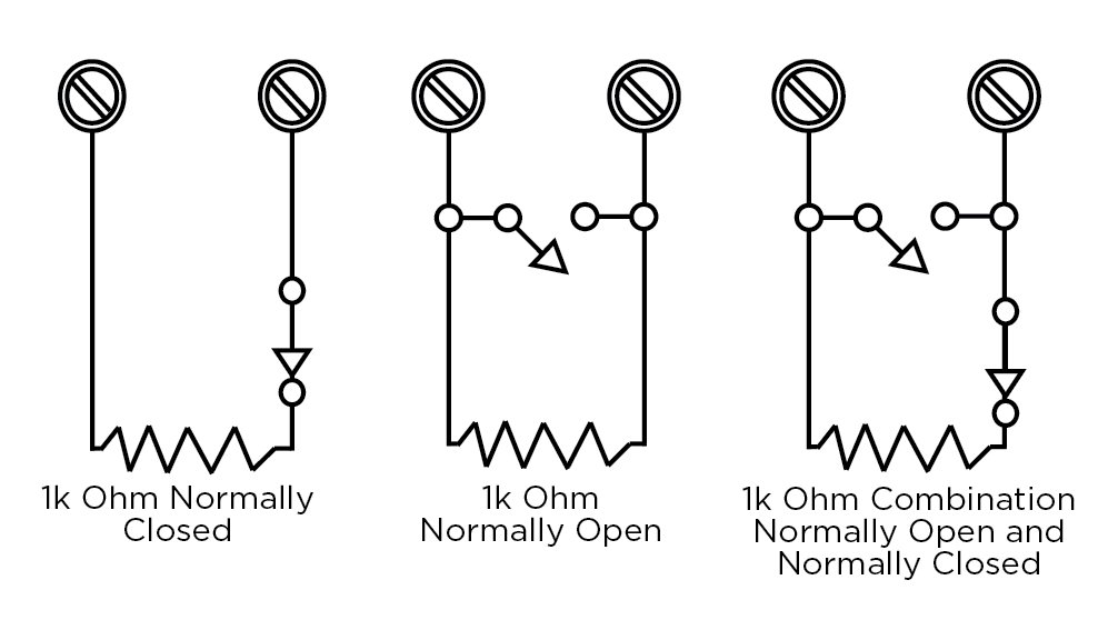
The voltage sensing terminal auto-senses the voltage across a 1 kΩ-10 kΩ End-of-Line (EOL) resistor connected to ground. Use DMP Model 311 1 kΩ resistors.

Dry contact sensing devices can be wired in series (normally closed) or in parallel (normally open) with any burglary protection zones.
resistors.png

Zone Response Time

A condition must remain present on a zone for 166 milliseconds before the XR650 detects it. Ensure detection devices used on the protection zones are rated for use with this delay.

Keyswitch Arming Zone

Using a keyswitch on an Arming zone allows you to arm and disarm selected areas without entering a user code.

Step 5: Wire Additional Hardware Components

Wire Relay Outputs

Dry Contact Relay Outputs

The XR650 provides two programmable auxiliary SPDT relays when equipped with two DMP Model 305 relays in the OUTPUT 1 and OUTPUT 2 sockets and a Model 431 Output Harness connected to the OUT1-OUT2 6-pin Header. Each relay provides one SPDT set of contacts that can be operated by the following functions:

  • Zone condition — Steady, Pulsing, Momentary, and Follow

  • 24-hour 7-day schedule — One on and one off time a day for each relay

  • Manual activation from the DMP keypad menu

  • Communication failure

  • Armed area annunciation

  • Ambush Alarm

  • Exit and Entry timers

  • System Ready

  • Late to Close

  • Panic Alarm

  • Ready

  • Armed

  • Disarmed

  • Burglary

  • Device Fail

  • Sensor Rest

  • Closing Wait

Contact Rating

Model 305 relay contacts are rated for 1 A at 30 VDC (0.35 power factor). Connect auxiliary power to the Relay Output 1 common terminal by installing the gray harness wire to terminal 7.

Note: Ensure the total current draw for all connected devices does not exceed the panel maximum current rating.

Model 431 Output Harness Wiring

Install the DMP 431 Output Harness on the 6-pin OUT1-OUT2 header. OUTPUT 2 uses the top three pins, and OUTPUT 1 uses the bottom three pins.

Contact

Color

Output 2 normally open

Orange with white stripe

Output 2 common

White with gray stripe

Output 2 normally closed

Violet with white stripe

Output 1 normally open

Orange

Output 1 common

Gray

Output 1 normally closed

Violet

Install the Model 860 Relay Module

Connect a Model 860 Relay Module to the OUTPUTS header on the XR650 to provide relays for outputs 3–6. Use these relays to provide electrical isolation between the alarm panel and other systems or to switch voltage for various control functions.

Power is supplied to the relay coils from a single wire connected to the panel auxiliary power terminal 7. The module includes one relay and three additional sockets for expansion of up to four relays.

Mount the Model 860 inside the panel enclosure using the 3-hole mounting pattern and plastic standoffs. Refer to the Model 860 Series Relay Module Installation Sheet for additional information.

Note: Relay contacts are rated for 1 A at 30 VDC (0.35 power factor).

Wire Annunciator Outputs

The four programmable annunciator outputs can be programmed to indicate panel zone activity or other system conditions. Annunciator outputs do not provide voltage but instead switch-to-ground voltage from another source. The outputs can respond to any of the conditions listed in Dry Contact Relay Outputs. The maximum voltage is 30 VDC at 50 mA.

Model 300 Harness Wiring

Install the DMP 300 Harness on the 4-pin OUTPUTS header to access outputs 3–6. For listed applications, devices connected to the outputs must be located in the same room as the panel.

Output

Color

Wire

3

Red

1

4

Yellow

2

5

Green

3

6

Black

4

Connect to Network

Connect to Ethernet

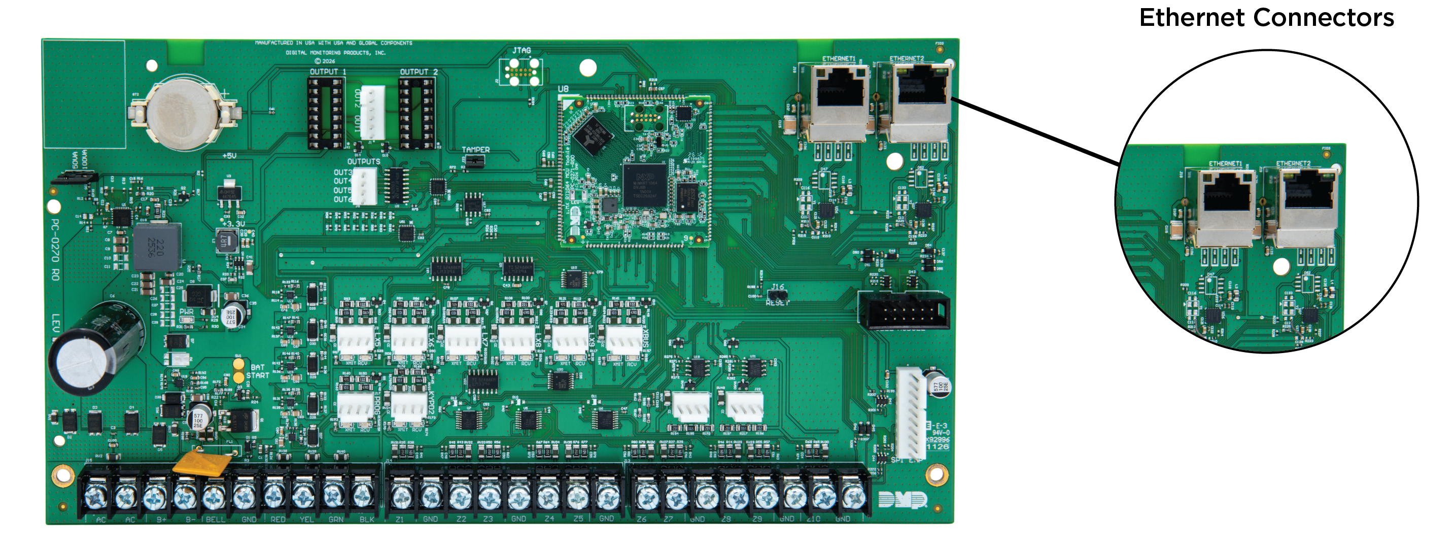
The XR650 provides two Ethernet ports for direct connection to an Ethernet network using a standard patch cable. The connector supports 100 Mb/s full-duplex operation with a maximum impedance of 100 kΩ. Ethernet connectivity is available on all XR650 models.

Ethernet Ports

The XR650 supports dual-NIC operation, which allows the panel to use two separate network connections:

  • ETHERNET1 — Use for the primary network connection. ETHERNET1 supports both WAN and LAN communication. This includes internet-based services like monitoring center communication, push notifications, Entré, Remote Link, and integrator connections. It can also communicate with LAN devices such as the 734N Network Access Control Module.

  • ETHERNET2 — Use for the secondary network connection. ETHERNET2 supports LAN communication only and does not connect to the internet or other WAN services.
ethernets.png

Ethernet LEDs

The two LEDs located on the top edge of the ETHERNET connectors indicate network connection status:

  • Link LED — Lights yellow when connected to a 100 Mb network and remains off when connected to a 10 Mb network.

  • Activity LED — Lights green to indicate a valid receive connection from the host network.

Network Transient Suppression

The Model 270 Transient Suppression Module provides surge suppression for the Ethernet network to protect DMP panels. Refer to the 270 Series Network Transient Suppression Module Installation Sheet for more information.

Connect to Cell

CAUTION: Do not install a cell module while the panel is powered on. Power down the panel before completing the steps below.

The CELL MODULE header, located to the right of the EXP header, is used to connect the DMP Model 263LTE Series Cellular Communicator. The communicator provides a fully supervised alarm communication path for the XR650.

Refer to the 263LTE Series Cellular Communicator Installation Guide for more information.

  1. Insert the flanged end of the standoff into the panel standoff hole.

  2. Align the 263LTE standoff hole with the standoff and the 263LTE 12-pin connector openings with the pins on the panel’s CELL MODULE connector. Press the module into place with even pressure on both sides of the board until the connector is fully seated.

Note: Do not misalign the cell module 12-pin connector with the CELL MODULE header. If necessary, remove the PCB from the enclosure to install the cell module. An antenna coax can also be connected directly to the cell module SMA connector when the coax enters the enclosure via conduit.
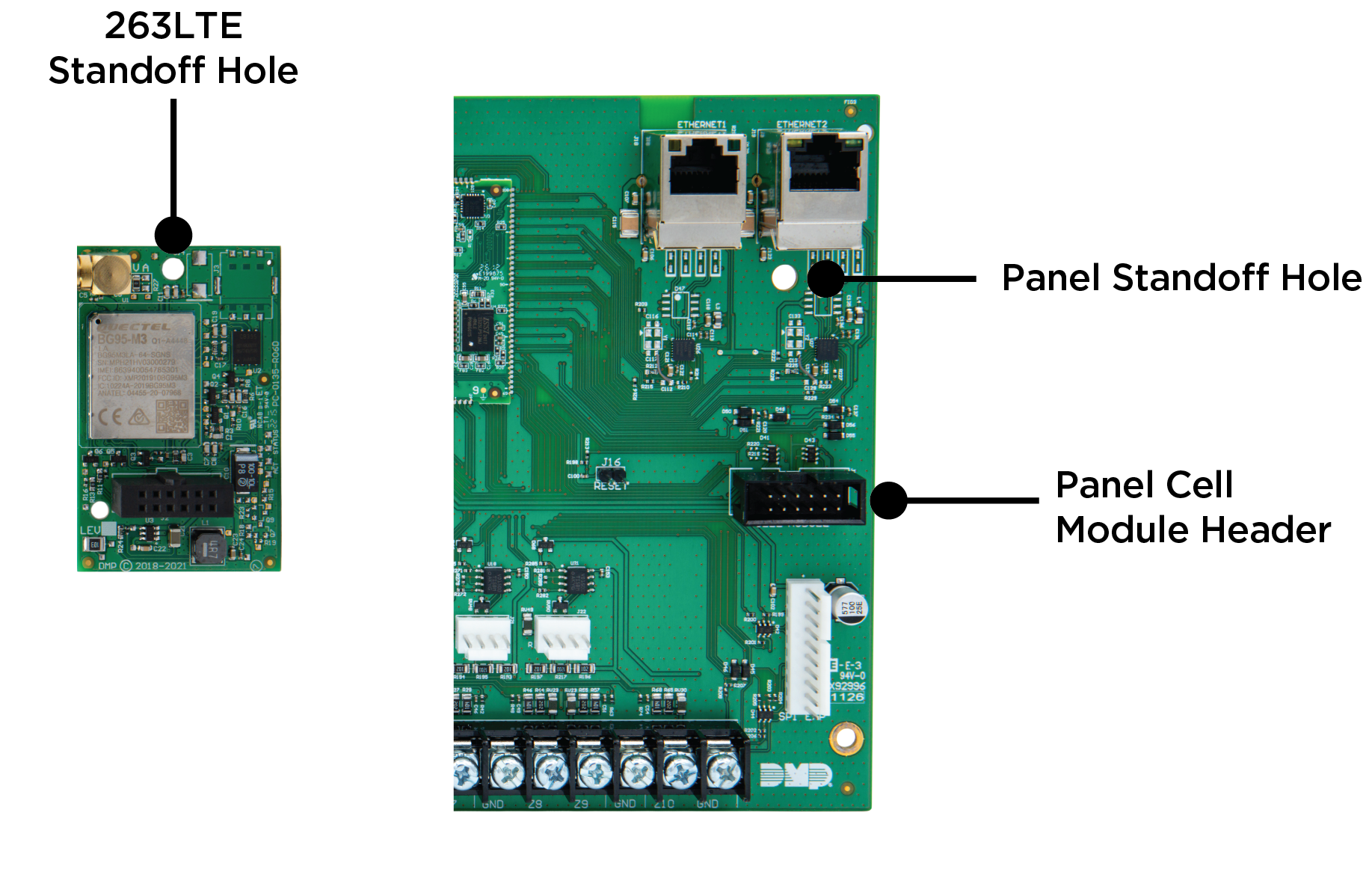
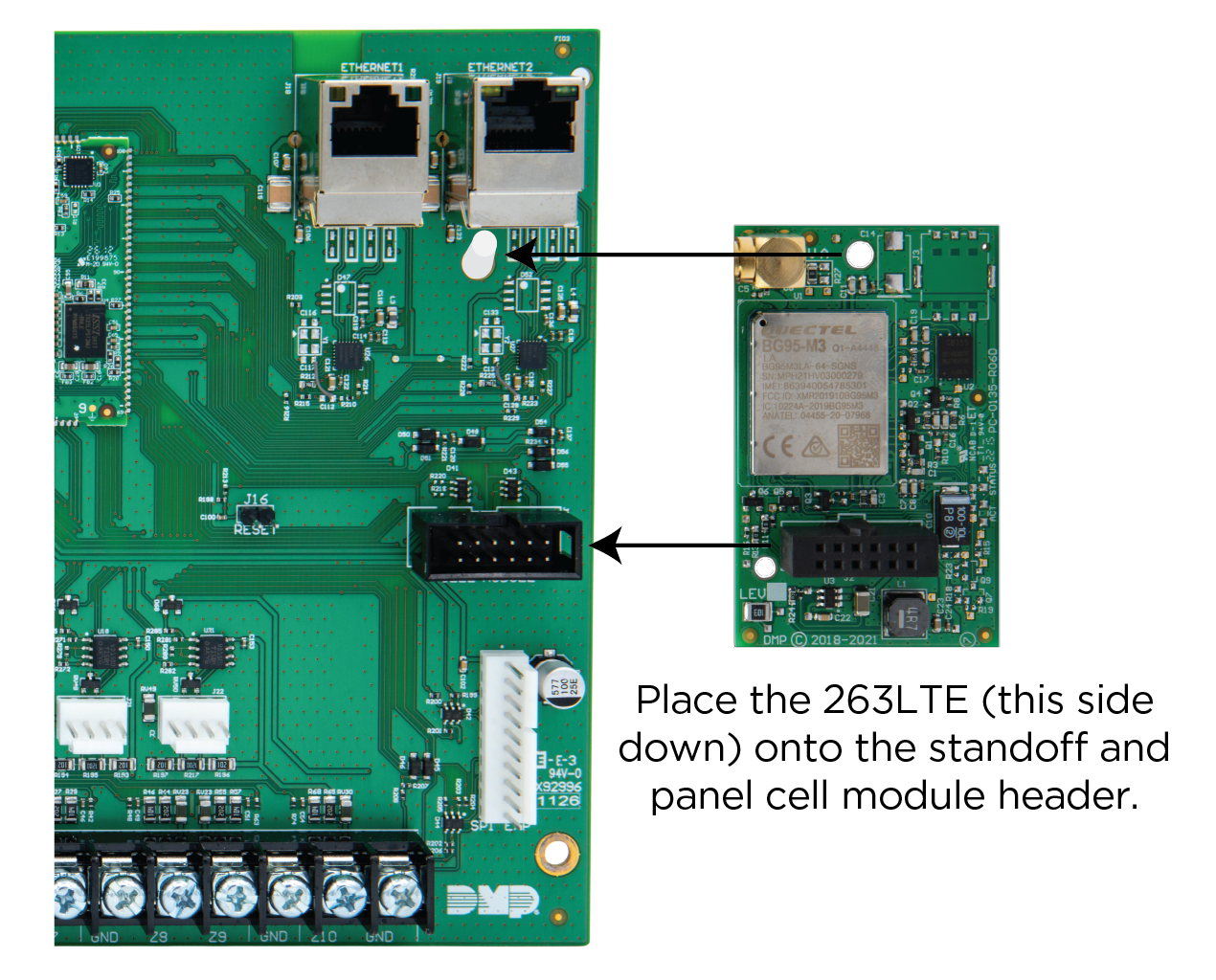
cell module installation.png
SMA antenna connection coax cable.png
  1. Attach a 381 cable to the SMA connector on the cell module.

  2. Place one of the supplied washers onto the other end of the 381 SMA connector and push the threaded end through an enclosure knockout.

  3. Place the second washer onto the threaded end extending through the knockout and secure the nut.

  4. Attach the included 383 antenna to the SMA connector.
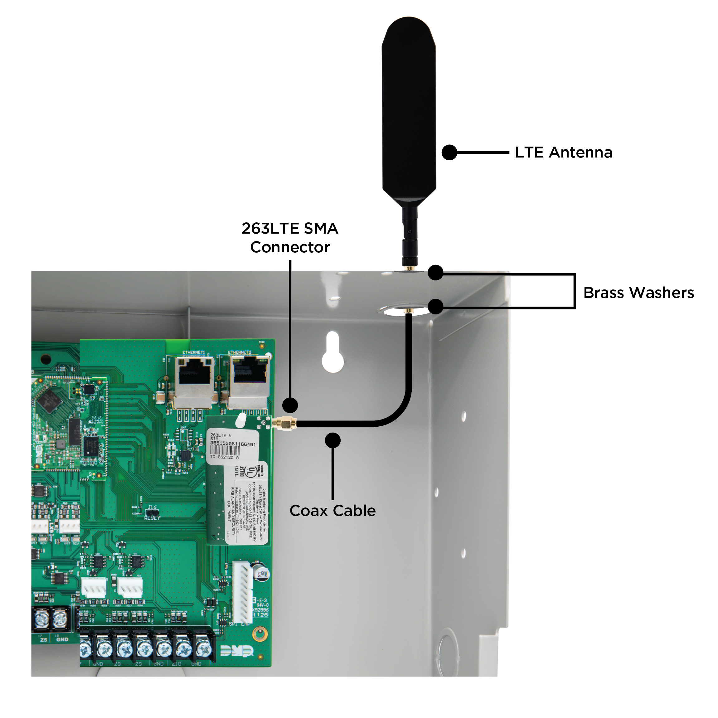
381 to antenna.png
Connect the Tamper

The TAMPER header connects to the optional DMP 306 Tamper Harness. The harness connects to one or more tamper switches inside the panel enclosure to detect unauthorized opening or removal.

Refer to the wiring diagram on the enclosure door for correct tamper switch wiring.

If the enclosure is opened or removed while one or more of the system areas are armed, the tamper alarm triggers. If all areas are disarmed, the panel indicates a tamper trouble.

Reset the Panel

The RESET header resets the panel’s microprocessor.
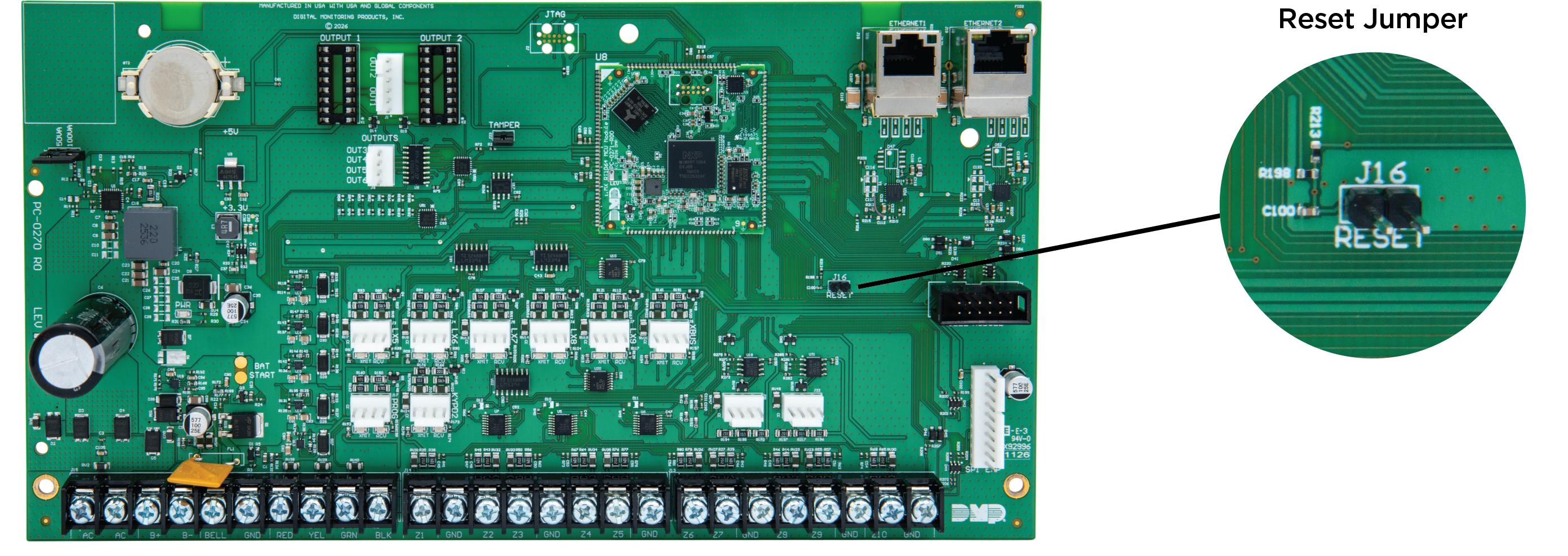
reset.png

Reset During Initial Installation

  1. Install the reset jumper before applying power to the panel.

  2. Connect the AC and battery power.

  3. Remove the reset jumper.

Reset During Normal Operation

  1. Install the reset jumper without powering down the panel.

  2. Remove the reset jumper after one or two seconds.

Note: Begin programming within 30 minutes of resetting the panel. If more than 30 minutes pass, reset the panel again before programming.

Connect Expansion Devices

Connect Wireless Devices

The XR650 supports the external DMP 1100XH/1100XHE Wireless Receiver through the XBUS. The receiver supports up to 500 wireless zones numbered 500–999.

Select a Location for the Receiver

Position the receiver centrally between the panel and the 1100 Series wireless transmitters. Use the transmitter you intend to install or an 1106 Series Universal Wireless Transmitter to perform an LED survey and verify communication at the desired location.

  1. With the transmitter cover removed, hold the transmitter at the desired location.

  2. Press the transmitter tamper/survey button to send data to the panel.

  3. Verify communication using the transmitter LED.

  4. If communication is faulty, relocate the transmitter or receiver and repeat the test.

Good Communication — The LED blinks on and immediately off each time the tamper/survey button is pressed or released. Repeat the test until five consecutive blinks are confirmed.

Poor Communication — The LED remains on for approximately 8 seconds or flashes multiple times in quick succession. Relocate the transmitter or wireless receiver and repeat the test until communication is confirmed.

Mount the Receiver

  1. Remove the cover from the 1100XH housing, then remove the PCB from the housing.

  2. Secure the receiver to the wall using the included #6 screws.

  3. Secure the wall tamper using one of the provided screws.

Wire the Receiver

  1. Connect the red, yellow, green, and black wires to the PANEL terminal on the 1100XH.

  2. Connect the other ends of the wires to the X-BUS on the XR650.

  3. Snap the cover back onto the receiver base.

Note: Do not use shielded wire between the panel and receiver. The 1100XH cannot operate when connected to the keypad bus.

Wireless Bus LEDs

The two LEDs above the XBUS header indicate communication between the panel and wireless receiver.

  • Left LED — Flashes green when the panel transmits data

  • Right LED — Flashes yellow when the panel receives data

Connect AX/LX-Bus Devices

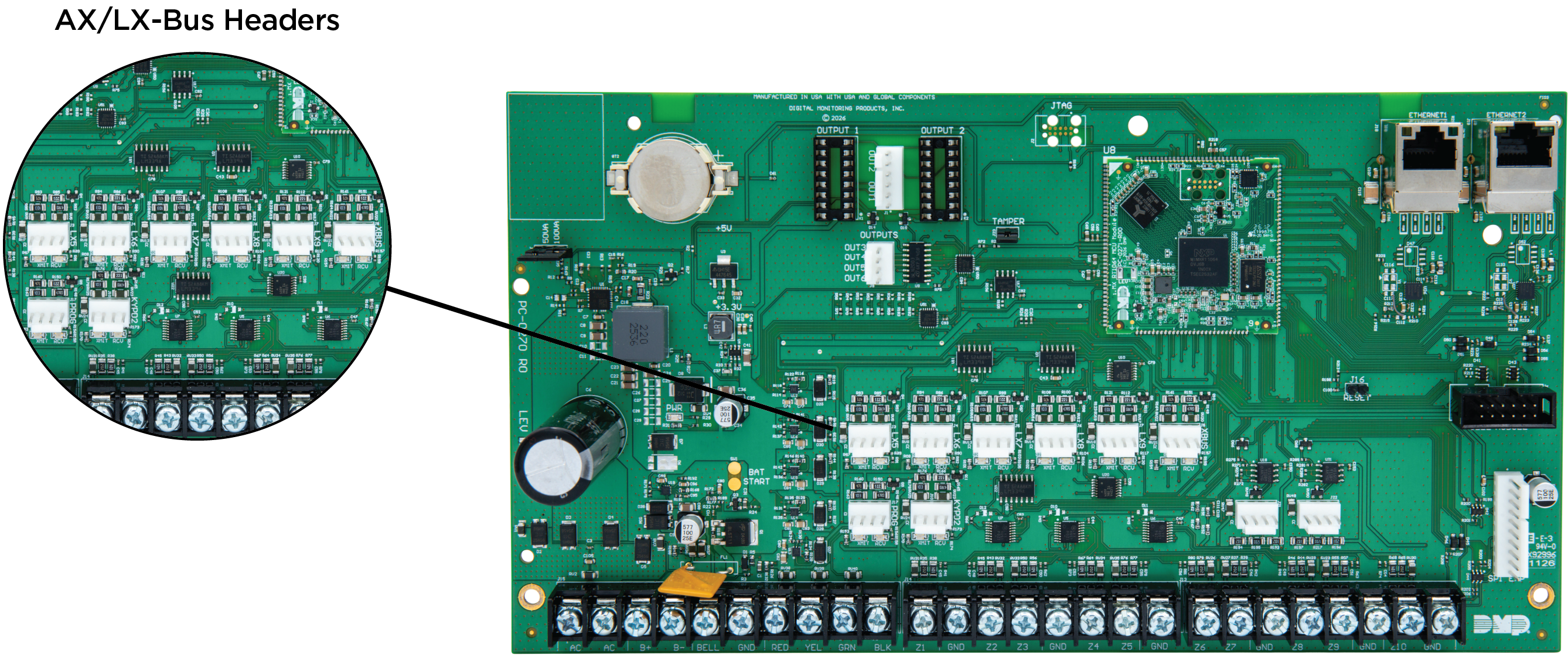
XR650 panels provide zone, output, and access control expansion through hardware modules connected to the AX/LX-Bus headers on the panel. The XR650 includes 5 AX/LX-Bus headers labeled LX5-LX9.
LX headers.png

LX-Bus

LX-Bus operation is compatible with hardwired zone and output expanders. Each LX-Bus represents the following addresses.

  • LX5 — zones/outputs 500-599

  • LX6 — zones/outputs 600-699

  • LX7 — zones/outputs 700-799

  • LX8 — zones/outputs 800-899

  • LX9 — zones/outputs 900-999

AX-Bus

AX-Bus operation is compatible with XR650 panels and DMP Models 734, 734E*, 734N, and 734N-POE Access Control Modules. Each access module provides one Form-C relay output and expansion zones.

AX-Bus operation is not compatible with addressable zone and output expanders. Each AX-Bus provides predetermined addresses for 734 Series Access Control Modules, including 16 addresses for door relay outputs and 64 addresses for expansion zones.

Device Addresses and 734 Series Zone Numbers

Addressable expanders and door controllers identify themselves to the control panel using their programmed address, which allows the panel to uniquely identify each device. The device address determines the zone, output, or door controller numbers assigned during programming.

Refer to the tables below and the device’s installation guide for addressing information.

Keypad Bus

Device Address

Zones

1

11-14

2

21-24

3

31-34

4

41-44

5

51-54

6

61-64

7

71-74

8

81-84

9

91-94

10

101-104

11

111-114

12

121-124

13

131-134

14

141-144

15

151-154

16

161-164

D = Device Address
Z = Zones

AX/LX-Bus

D

Z

D

Z

D

Z

D

Z

D

Z

501

501-504

601

601-604

701

701-704

801

801-804

901

901-904

505

505-508

605

605-08

705

705-708

805

805-808

905

905-908

509

509-512

609

609-612

709

709-712

809

809-812

909

909-912

513

513-516

613

613-616

713

713-716

813

813-816

913

913-916

517

517-520

617

617-620

717

717-720

817

817-820

917

917-920

521

521-524

621

621-624

721

721-724

821

821-824

921

921-924

525

525-528

625

625-628

725

725-728

825

825-828

924

925-928

529

529-532

629

629-632

729

729-732

829

829-832

929

929-932

533

533-536

633

633-636

733

733-736

833

833-836

933

933-936

537

537-540

637

637-640

737

737-740

837

837-840

937

937-940

541

541-544

641

641-644

741

741-744

841

841-844

941

941-944

545

545-548

645

645-648

745

745-748

845

845-848

945

945-948

549

549-552

649

649-652

749

749-752

849

849-852

949

949-952

553

553-556

653

653-656

753

753-756

843

853-856

953

953-956

557

557-560

657

657-660

757

757-760

857

857-860

957

957-960

561

561-564

661

661-664

761

761-764

861

861-864

961

961-964

*The 734E only communicates through the AX-Bus and does not use the keypad bus. When a 734E is programmed on a bus, all devices connected to that bus only operate if they are encrypted.

AX/LX-Bus LEDs

The two LEDs located above each AX/LX-Bus header indicate data transmission and reception:

  • Left LED — Flashes green when the panel transmits AX/LX-Bus data

  • Right LED — Flashes yellow when the panel receives AX/LX-Bus data

Step 6: Set Up Wireless Keypads

Before you begin, ensure the wireless keypad is mounted and ready for association.

To enable wireless keypad association on the XR650, reset the panel 3 times to allow the keypad bus transmit light to begin flashing between each reset.

The following occurs:

  • For 60 seconds, the panel listens for wireless keypads that are in RF Survey and have not been programmed or associated with another panel.

  • Wireless keypads are assigned to the first available device position in Device Setup based on the order in which they are detected.

  • The keypad logo turns green when the keypad is successfully associated with the panel.

Note: Up to 7 wireless keypads are allowed on each panel.

LCD Wireless Keypad
  1. At the keypad, press and hold the Back Arrow and CMD until SET BRIGHTNESS displays.

  2. Enter the 3577 (INST), then press CMD.

  3. Press KPD RF to start the RF survey communication. The keypad displays its wireless serial number and RF SURVEY.

Power/Armed LED
The keypad power/armed LED turns red when communication with the panel receiver has not yet been established. The LED turns green once communication is successful.

Wireless Graphic Touchscreen Keypad
  1. At the keypad, go to Options in the carousel menu.

  2. In Options, press the Installer Options icon.

  3. Enter 3577 (INST), then press CMD.

  4. Press KPD RF to start the RF Survey communication. The keypad displays its wireless serial number and RF SURVEY.

Power/Armed LED
The keypad power/armed LED turns red when communication with the panel receiver has not yet been established. The LED turns blue once communication is successful.

Last updated: